Soil cover system design for mine waste dumps
/
Surface water and groundwater surrounding a mining operation can be significantly affected by contaminated seepage from the Acid Rock Drainage (ARD) in waste-dumps and tailing deposits. An evaluation for prevention and mitigation of environmental impacts generated by the DAR is necessary to minimize impact to the environment.
Mining dumps are rock deposits without interest mineral concentrations resulting from a mining explotation. Frequently, the material of the dump is in contact with the ground, therefore, any Acid Rock Drainage reaction that triggers this material was filtered to the soil and may damage groundwater or springs in the area.
Aware of the importance of preserving the ecosystem and the interests of mining companies, Gidahatari has developed an environmental, innovative and economical coverage. We have adapted the design of coverage to a lower cost, made with materials available in the area, obtaining the desired technical specifications.
Bellow is shown a description of the methodology for the design of multilayer coverage in mining waste-dumps for purposes of a mine closure plan.
Legal Framework
In Peru, the main environmental protection dispositions applicable to the design of coverage for mining dumps are in the Law No. 28090, law that regulates a mine closure plan, that at the same time obeys the rules set out in the Text of General Mining law, approved by the Supreme Decree 014-92-MS, and law No. 28271, a law that regulates the environmental liabilities of mining.
Conceptual Framework
Every mining company has into their operations waste-dumps where they storage rocks and waste material from extraction of the main mineral. These rocks contain by nature sulphides that, in contact with air (oxygen), tend to oxidize and, when mixed with water from precipitation, generate acid drainage that flows into the ground causing contamination.
Acid rock drainage is generated when sulfide oxidation and acid generation beyond the capacity of neutralization. One way of controling all this production of acid drainage requires the sulfide minerals to not be in contact with oxygen, however this is not completely reachable. The basic concepts for acid rock drainage prevention are the reduction of oxygen income and preventing contact with water that could act as a transport medium for oxidized products.

Figure 1. Scheme of the factors that affect the oxidation of the sulphide rocks 1
The main approaches of acid rock drainage mitigation is to apply methods to:
- Minimize the oxygen supply.
- Minimize the infiltration of water and/or leaching.
- Minimize, eliminate or isolate the sulphide minerals.
- Control the pH of water that infiltrates (ensure water alkalinity).
- Maximize the availability of mineral acid neutralizers.
- Control the growth of bacteria and biogeochemical processes.
- Allow revegetation.
The coverage design proposed by Gidahatari should reduce leaks to the standards set out by regulators. The cover system must allow the vegetation at the top, allowing the dump to regain a natural look in the ecosystem.
The type of vegetation, their performance regarding water availability and rooting depth will be tested in this research. Vegetation should be consuming most of the precipitation water, with a soil layer that allows its full development, but taking care that the roots do not damage lower layers.
Other factors such as stability, erosion, and performance over time will also be considered in evaluating alternatives. The use of materials of the area for the coverage system is prioritized.

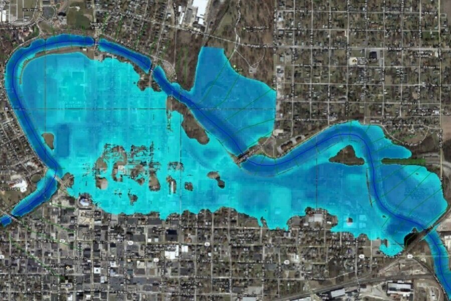
Figure 2. Conceptual scheme of a waste-dump coverage and its hydrogeology 2.
Methodology
The main plan work steps proposed for the coverage design is shown in the figure bellow:
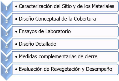
Figure 3. Steps for a coverage design evaluation.
1. Site and materials characterization
At first, a fieldwork is performed to identify the location of waste-dumps and terrain around. Fieldwork includes the evaluation of soil profiles in pits and the identification of water bodies around and their status.

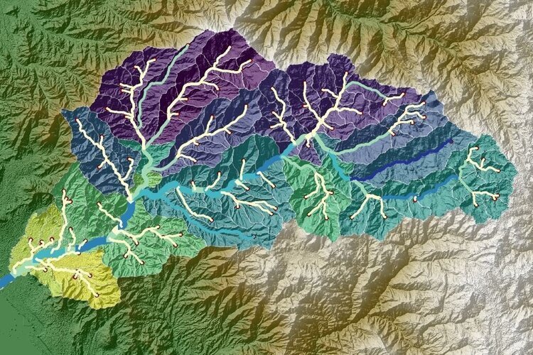
Figure 4. Waste-dump hydrogeology.
It considers the installation of deep piezometers to intercept deep infiltration and shallow piezometers in the discharge areas to the courses of superficial water.
Chemical samples of the main water courses are taken, monitoring points, natural springs and upwelling of leachate.
It is also contemplated the collection of initial and current topography data, Installation Details of dump deposits, data interception systems, weather, rainfall, flow records and water chemistry.

Figure 5. Tailings leak flow lines and location of shallow and deep piezometers.
The field exploration also focuses on identiying materials to lend the coverages.
2. Conceptual coverage design
With hydrologic, hydrogeological and chemical information the conceptual model that evaluates the applicability, advantages and limitations of coverage systems is built.
This phase includes a preliminary hydrogeological model that provides referential values on the water balance of the waste-dump and groundwater regime.
The purpose of the coverage system is to prevent the discharge of contaminated drainage. At this stage of the preliminary assessment, coverage alternatives that meet environmental criteria is evaluated using the most effective and lowest cost. This selection also goes along with aspects of performance over time, maintenance cost, stability and erosion.
It is also an evaluated aspect like material availability, giving priority to the closest materials to the dump.
3. Laboratory tests
The borrow material and dump material will be processed through a crushing process in different sizes. It will focus on the distribution that gets the least amount of spaces and, therefore, a lower hydraulic conductivity.

Figure 6. Relation between the percentage of voids and saturated hydraulic conductivity 3.
The processed material will be analyzed pure and in combinations to obtain hydraulic conductivity values at different levels of compaction. Dynamic load analysis will be conducted to assess the dynamic hydraulic parameters such as specific yield and specific storage. These analysis will be performed with a numerical model including the scale of the test.
4. Detail design
With the values of hydraulic parameters for different combinations of processed material, a numerical model which simulates infiltration of precipitation and its passage through the different layers is built. An infiltration flow analysis is made for each combination, optimizing at the same time the distribution of thickness in each layer.
The model will be calibrated with a laboratory test of the distribution of the multilayer system in saturated conditions. Once calibrated the model, the hydrogeological response in average conditions throughout the year is represented.

Figure 7. Coverage test in saturated conditions implementation.
The numerical model provides annual estimations of every layer infiltration and a waste-dump calibrated water balance.
5. Complementary closure measures
After defining the coverage system and based on the hydrogeological characterization, the closure measure for waste-dumps will be proposed following these aspects:
● Groundwater monitoring network implementation.
● Infiltration monitoring network implementation.
● Groundwater interception system.
● Perimeter channel systems.
6. Revegetation and performance assessment
With the coverage option chosen, an in-situ cell where a soil layer is put for vegetation development is built.
The objective of this test is to evaluate in the field the vegetation system and coverage system performance. The period of this test is long since a complete growth of vegetation and development of infiltration to the drainage area is considered. The type of vegetation to be used is obtained from local flora, focusing on one type of non deep rooted vegetation. For cases where field capacity is exceeded, it will measure surface flows.
Test cells are useful for evaluating the efficiency to a greater scale multilayer cover system. The infiltration values are evaluated over a year. If differences were registered between calculated and observed values, the model would be recalibrated and remedial action would be taken.
Numerical Tools
MODFLOW 2005 with unsaturated flow zone (UFZ)
MODFLOW is the code for groundwater modeling in 3D based on finite differences developed by the U.S. Geological Survey (USGS). MODFLOW simulates static and transient flow in an aquifer system that can be irregular confined, unconfined, or mixed. Flow of wells, recharge, evapotranspiration, drains, river beds can also be simulated by MODFLOW.
The hydraulic conductivities for each layer can change spatially and be anisotropic, so the storage coefficient may be heterogeneous. In addition to the simulation of groundwater flow, the scope of MODFLOW has been expanded to incorporate solute transport capabilities and management of groundwater.
The new package of MODFLOW-2005 called unsaturated flow zone (UFZ1) Package was developed to simulate the flow and storage in the unsaturated zone and flow in evapotranspiration and recharge. The package also calculates surface runoff in rivers and lakes.

Figure 8. Flow in one dimension in the unsaturated zone coupled with a groundwater model in a three dimensions
References
1. International Network for Acid Prevention (INAP), Global Acid Rock Drainage (GARD), Chapter 2
2. Mine Environment Neutral Drainage Program (MEND), 2004a. Design, construction and performance monitoring of cover systems for waste rock and tailings. Report 2.21.4, O’Kane Consultants Inc., (Eds.), Natural Resources Canada.
3. Mine Environment Neutral Drainage Program (MEND), 1995. Hydrogeology of Waste Dumps. Natural Resources Canada.
4. Niswonger, R.G., Prudic, D.E., and Regan, R.S., 2006, Documentation of the Unsaturated-Zone Flow (UZF1) Package for modeling unsaturated flow between the land surface and the water table with MODFLOW-2005: U.S. Geological Techniques and Methods Book 6, Chapter A19, 62 p.
Download this information in PDF format here.